


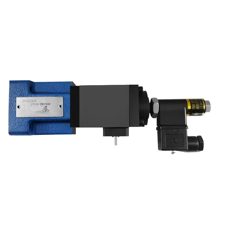
2FRE Type Proportional flow control valve 2-way version for Rexroth
- Valve with a pressure compensator for the pressure compensated control of a flow
- Actuation via a proportional solenoid
- With electrical position feedback of the control orifice
- The position transducer coil can be axially moved making the zero point adjustment of the control orifice easy, without having to touch the electron-ics (electrical-hydraulic)
- Flow control is possible in both directions by using a rectifier sandwich plate
Product features
◉ Valve with a pressure compensator for the pressure compensated control of a flow
◉ Actuation via a proportional solenoid
◉ With electrical position feedback of the control orifice
◉ The position transducer coil can be axially moved making the zero point adjustment of the control orifice easy, without having to touch the electron-ics (electrical-hydraulic)
◉ Flow control is possible in both directions by using a rectifier sandwich plate
Functional section
The type 2FRE ... proportional flow control valves have a 2-way function. They can, from a applied electrical command value, regulate flow which is pressure and temperature compensated.
They basically comprise of the housing (1), proportional solenoid with inductive position transducer (2),measuring orifice (3), pressure compensator (4) as well as the optional check valve (5).
Proportional flow control valve 2FRE 6 B:
The setting of the flow is determined (0 to 100 %) at the command value potentiometer. The applied command value adjusts, via the applifier as well as the proportional solenoid, the measurement orifice (3). The position of the measurement orifice (3) is obtained by the inductive position transducer. Any deviations from the command value are compensated for by the feedback control.
The pressure compensator (4) holds the pressure drop at the measurement orifice (3) at a constant value. The flow is, therefore load compensated.
The small temperature drift is achieved due to the design of the measurement orifice.
At a 0% command value the measurement orifice is closed.
In the case of a loss of power or a cable break at the position transducer the measurement orifice closes.
From a 0 % command value a jump free start is possible Via two ramps within the electrical amplifier, it is possible to delay the opening and closing of the measurement orifice.
Via the check valve (5) a free flow is possible from B to A.
Proportional flow control valve type 2FRE 6 A
The function of this valve is in principle the same as valve type 2FRE 6 B:
To suppress the start-up jump when the measurement orifice (3)(command value > 0 %) is open, there is provision for the pressure compensator (4) to be held closed via port P (6). The intemal connection (7) between port A and the pressure compensator (4) is plugged. Via the external port P (6) the pressure in port P, before the directional valve (8) acts on the pressure compensator (4) and holds it against the spring force (9) in the closed position.If the directional valve (8) is switched over from P to B, then the pressure compensator(4) moves from the dosed position into the regualting position and the start-up jump is thereby avoided.
Technical data
(for applications outside these parameters, please consult us!)
|
Max. permissible operating pressure, port A |
21 (port A) |
||||||
|
Flow q, max.(L/min) |
Type |
2QE |
3Q |
6Q |
10Q |
16Q |
25Q |
|
|
2 |
3 |
6 |
10 |
16 |
25 |
|
|
|
to 10MPa |
0.015 |
0.015 |
0.025 |
0.05 |
0.07 |
0.1 |
|
|
to 21MPa |
0.025 |
0.025 |
0.025 |
0.05 |
0.07 |
0.1 |
|
Max. leakage flow at command value 0%(L/min) |
△p(A → B) |
||||||
|
5MPa |
0.004 |
0.004 |
0.004 |
0.006 |
0.007 |
0.01 |
|
|
10MPa |
0.005 |
0.005 |
0.005 |
0.008 |
0.01 |
0.015 |
|
|
21Mpa |
0.007 |
0.007 |
0.007 |
0.012 |
0.015 |
0.022 |
|
|
Minimum pressure differential (MPa) |
0.6 to 1 |
||||||
|
△p freereturn flow(B →A) |
see diagram on page 69 |
||||||
|
Pressure flow relationship: inlet/outlet pressure |
see diagram on page 69 |
||||||
|
Flow stability |
see diagram on page 69 |
||||||
|
Hysteresis |
±1%Qmax |
||||||
|
Repeatability |
< 1%Qmax |
||||||
|
Degree of contamination(μm) |
≤ 20 (We recommend a filter with a minimum retention rate of 10) |
||||||
|
Pressure fluid |
Mineral oil (for NBR seal) or Phosphate ester (for FKM seal) |
||||||
|
Viscosity range(mm²S) |
2.8 to 380 |
||||||
|
Pressure fluid temperature range(°C) |
-20 to +70 |
||||||
|
Installation |
optional |
||||||
|
Electrical |
|
|
Voltage type |
DC |
|
Coil resistance of solenoid(Ω) |
Cold value at 20°C 5.4, Max. warm value 8.2 at +50°C |
|
Coil resistance of transducer(Ω) |
at 20°C 1 - 56, II - 56, III - 112 |
|
Max. Power(VA) |
50 |
|
Inductivity(mH) |
6 to 8 |
|
Oscillator frequency(kHz) |
2.5 |
|
Surroundings temperature(°C) |
Max. 50 |
|
Amplifier |
VT - 5010S30 Demand of insulation IP65 |
Characteristic curves
(measured at ν = 36 × 10⁻⁶ m²/s; t = 50°C )
|
Frequency response characteristic curve |
||
|
Input signals(%) |
Qmin to Qmax Tu+Tg(ms) |
Qmax to Qmin Tu+Tg(ms) |
|
0 - 100 |
50 |
60 |
|
10 - 90 |
45 |
50 |
|
25 - 75 |
40 |
45 |
![]() Public Mailbox: info@changjia.com
Public Mailbox: info@changjia.com
Contact us