DBE,DBEM TyPe Proportional Pressure Relief Valve For Rexroth
- Encased in block
- Optional additional maximum pressure limita-tion by means of a spring loaded pilot contro lvalve
- Valve and electronic control form one source
Product features
◉ For subplate mounting:
◉ Encased in block
◉ Optional additional maximum pressure limita-tion by means of a spring loaded pilot contro lvalve
◉ Valve and electronic control form one source
Functional section
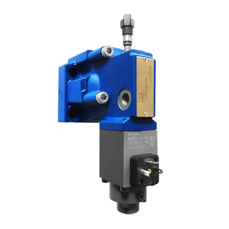
These valves basically consist of the pilot control valve(1)with proportional solenoid (2) and the main valve(3) with main spool insert (4)
◉ Type DBE:
The adjustment of the pressure is command value dependent via a proportional solenoid (2). The pressure present in port A acts on the underside of the main spool (4). At the same time this pressure acts on the spring loaded side of the main spool (4) via orificies (5). The hydraulic force acts on the pilot poppet . (6)When the hydraulic force over comes the solenoid force then the pilot poppet (6) opens. Due to the fact that the pilot oil can now flow to tank via port Y, a pressure drop occurs at the main spool (4)which acts on the main spool and lifts it against the force of the retumn spring . The connection from A to B is opened and there is no longer any increase inpressure.
◉ Type DBEM:
Optionally the valve can be supplied with an additional spring loaded pilot control valve for maximum pressure safety (redundant pressure safety).
Technical data
(For application outside these parameters, Please consult us!)
|
Hydraulic data |
|||||
|
Max. operating pressure |
Ports A, B and X |
(MPa) |
31.5 |
||
|
Return pressure |
(MPa) |
(MPa) |
Port Y, separate and at zero pressure to tank |
||
|
Max. settable pressure |
(MPa) |
(MPa) |
5, 10, 20, 31.5, same as pressure stage |
||
|
Min. settable pressure |
(MPa) |
(MPa) |
see characteristic curves |
||
|
Max. pressure safety |
(MPa) |
(MPa) |
settable pressure |
||
|
5 |
10 |
20 |
|||
|
1 to 6†‡ |
1 to 12‡ |
1 to 22‡ |
|||
|
Max. pressure safety/Adjustable pressure range |
(MPa) |
(MPa) |
rated. pressure |
||
|
5 |
10 |
20 |
|||
|
6 to 8 |
12 to 14 |
22 to 24 |
|||
|
Max. flow |
(L/min) |
(L/min) |
10 |
20 |
30 |
|
200 |
400 |
600 |
|||
|
Pilot flow |
(L/min) |
(L/min) |
0.7 to 2 |
||
|
Linearity |
(%) |
(%) |
± 3.5 |
||
|
Repeatability |
(%) |
(%) |
< ± 2 |
||
|
Typical variation |
(%) |
(%) |
< ± 2 Max. pressure |
||
|
Hysteresis |
(%) |
(%) |
With surge ± 1.5 of Max.pressure, Without surge ± 4.5 of Max.pressure |
||
|
Switching time |
(ms) |
(ms) |
30 to 150 |
||
|
Pressure fluid |
Mineral oil (for NBR seal),Phosphate ester (for FPM seal) |
||||
|
Viscosity range |
(mm²/s) |
(mm²/s) |
2.8 to 380 |
||
|
Pressure fluid temperature range |
(℃) |
(℃) |
-20 to +70 |
||
|
Degree of contamination |
(μm) |
(μm) |
< 20(recommendation 10) |
||
|
Electrical technical data |
|||
|
Amplifier |
VT-200/240 supplied with valve together |
||
|
Supply voltage |
DC |
||
|
Min. control current |
(A) |
(A) |
0.1 |
|
Max. control current |
(A) |
(A) |
0.8 |
|
Coil resistance |
(Ω) |
(Ω) |
Cold value at 20℃ is 19.5; Max. warm value is 28.8 |
|
Pressure fluid temperature range |
(℃) |
(℃) |
+50 |
|
Working state |
Continue |
||
|
Valve protection |
IP65 |
||
|
Electrical connections |
plug |
||
|
Notice |
||
|
The fluid must be filtered. Minimum filter fineness is 20 μm. |
||
|
The tank must be sealing up and an air filter must be installed on air entrance. |
||
|
Products without subplate when leaving factory, if need them, please ordering specially. |
||
|
Valve fixing screws must be high intensity level (class 10.9). Please select and use them according to the parameter listed in the sample book. |
||
|
Roughness of surface linked with the valve is required to Ra 0.8 μm. |
||
|
Surface finish of mating piece is required to 0.01/100mm. |
Transient functions with stepped electrical input signals
Contact us